Numerical Analysis of a Low-Cost Spherical Air Bearing for CubeSat ADCS Testing
CFD (ANSYS Fluent) study of a flat-orifice, 13-inlet (1 central + 12 peripheral) spherical air bearing concept: ~279 N net load capacity at h=100 µm and ~1.2 N/µm static stiffness.
TL;DR: To reduce friction and parasitic torques in ground-based CubeSat ADCS verification, I numerically evaluated a low-cost, machinable, flat-orifice (straight/unpocketed) spherical air bearing with multi-supply (13 inlets) using ANSYS Fluent.
Problem
On-orbit, satellites operate close to a torque-free environment. On the ground, however, ADCS validation is often distorted by:
- mechanical contact and friction,
- parasitic external torques,
- gravity torque due to CoM–CR (Center of Mass–Center of Rotation) offset.
A near-frictionless support is therefore crucial for meaningful ADCS testing.
Why a Spherical Air Bearing?
Spherical air bearings provide a low-friction, microgravity-like support for satellite simulators.
In this project, the design choices prioritized cost and manufacturability:
- Orifice-restricted instead of porous-restricted, and
- Unpocketed (straight) orifices instead of pocketed geometries to improve dynamic stability.
Unpocketed designs are generally less prone to pneumatic hammer instabilities associated with trapped pocket volumes.
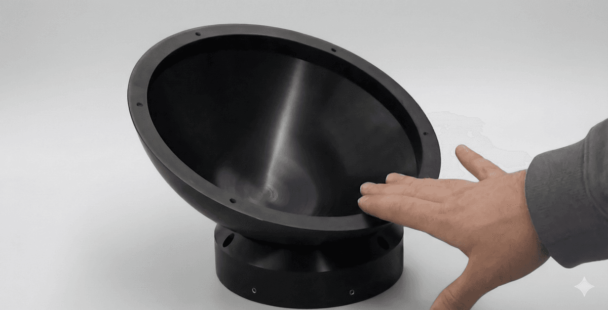
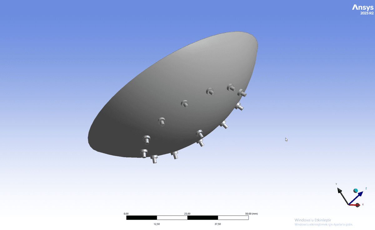
Design: Multi-Supply Architecture (13 Inlets)
The socket geometry is fed by 13 inlets: 1 central plus 12 peripheral.
Geometry & Supply Conditions
| Parameter | Value |
|---|---|
| Socket diameter (D) | 80 mm |
| Nominal film thickness (h) | 100 µm |
| Number of inlets | 13 (1 central + 12 peripheral) |
| Inlet pressure (gauge) | 1 bar |
| Outlet pressure (gauge) | 0 Pa (vented to atmosphere) |
Method: ANSYS Fluent CFD Setup
The simulations were performed in Fluent assuming compressible ideal gas and laminar flow.
Solver & Models
- Solver: Pressure-based, steady, absolute
- Viscous model: Laminar
- Density: Ideal gas
- Viscosity: Sutherland (three-coefficient)
- Energy equation: Enabled
- Pressure–velocity coupling: Coupled
- Pressure discretization: PRESTO!
- Momentum/Density/Energy: Second Order Upwind
- Convergence aid: Pseudo-time stepping
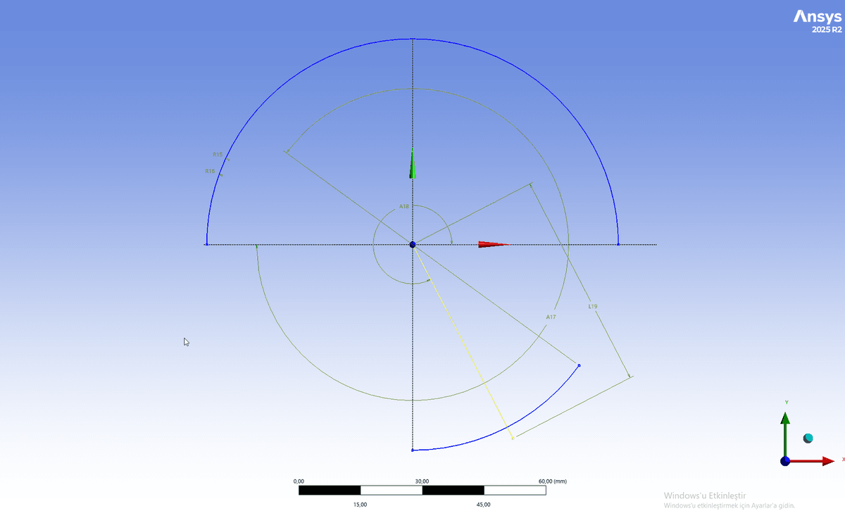
Mesh — Local Refinements
Thin-film regions require strong local refinement near inlet–film junctions due to steep gradients.
| Region / Feature | Sizing |
|---|---|
wall_sphere, wall_socket, outlet surfaces | Face sizing: 0.15 mm |
| Wall surface connecting inlet to the film | Face sizing: 0.20 mm |
| Inlet–film junction edges | Edge sizing: 0.05 mm |
| Inner & outer outlet edges | Edge sizing: 0.10 mm |
Performance Metrics
Two main performance metrics were used:
- Net load capacity (W)
- Static stiffness (K)
Definitions:
W = ∫ (p − Patm) * cos(θ) dA
K = − dW/dh
With multiple inlets, the pressure field varies with azimuth (φ), so the general (angular) formulation is considered.
Results (Key Findings)
1) Net Load Capacity (h = 100 µm)
On wall_sphere (lift direction 0, −1, 0) in Fluent:
| Component | Value |
|---|---|
| Pressure force | 279.52869 N |
| Viscous force | −0.3402059 N |
| Total net load (W) | 279.18848 N |
The viscous contribution is negligible compared to pressure; load capacity is dominated by the pressure field.
2) Static Stiffness (95–100 µm interval)
Using a secant approximation:
- K ≈ 1.2 N/µm
- (approximately 1.2 × 10⁶ N/m)
This indicates a meaningful restoring response to small changes in film thickness.
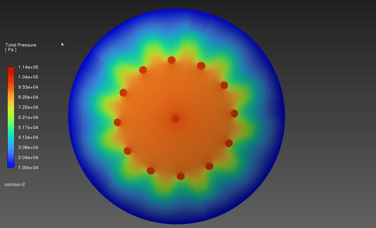
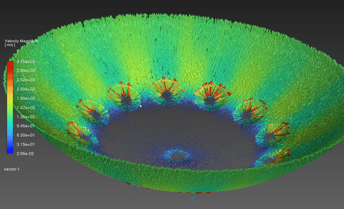
3) Pressure & Flow Field Observations
-
Pressure peaks around the inlets and decays toward the outlet.
-
Reported gauge pressure range (approx.):
- pg,max ≈ 1 × 10⁵ Pa
- pg,min ≈ 2.54 × 10⁴ Pa

In the flow field, local acceleration appears near inlet regions:

Local Linear Model for W(h)
A local linear approximation around 100 µm:
W(h) ≈ W100 + K(100 − h)
W100 = 279.18848 N,  K ≈ 1.2 N/µm
(h in µm)| h (µm) | W(h) (N) |
|---|---|
| 90 | 291.18848 |
| 95 | 285.18848 |
| 100 | 279.18848 |
| 105 | 273.18848 |
| 110 | 267.18848 |
Design Decisions & Trade-offs
Unpocketed (straight) orifice choice
- ✅ Improved dynamic stability (more resistant to pneumatic hammer)
- ⚠️ Single-orifice load may be limited → mitigated via multi-orifice supply
Multi-supply (13 inlets)
- ✅ Potentially higher load capacity and stiffness through a more favorable pressure profile
- ✅ More distributed support, which can help produce a restoring moment under tilt conditions
Limitations
- Results are reported for a single supply architecture and around a limited film-thickness neighborhood.
- A broader parametric sweep (h, supply pressure, orifice diameter) and tighter solution verification are left for future work.
Next Steps
- Quantitative comparison with a single-orifice reference geometry
- Parametric scan over h, supply pressure, and orifice diameter → W(h), K(h) curves
- Time-dependent studies on dynamic stability (pneumatic hammer) and sensitivity to tilt / CoM–CR offset
- Experimental validation of the CFD model